Ratcam v1
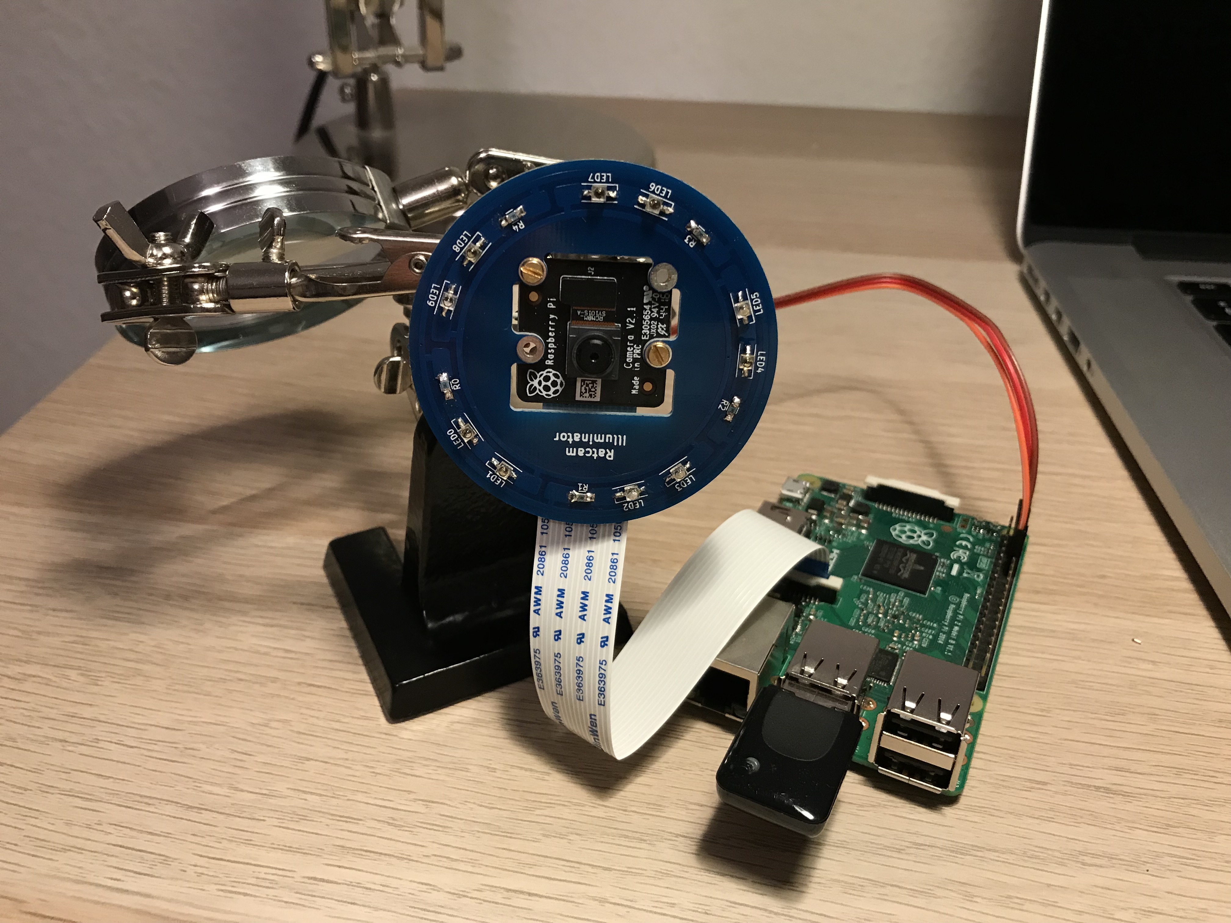
Ratcam allows you to control your RaspberryPi camera through a Telegram bot, and alerts you when movement is detected, by sending photos and videos.
The idea came to me when I found traces of mice in my house; rather than adopting drastic measures (and having to deal with the remains), I wanted to figure out from where they entered.
I developed a initial version, but I'd like to make some improvements to it.
Project status
- ONGOING Printed circuit board illuminator that controls IR LEDs in PWM
- OK Kicad script support for circular placement and routing
- OK Component selection and PCB manifacturing
- OK Test hardware PWM
- ONGOING Re-aligning pin header and camera
- ONGOING Software modularization to enable/disable features.
- TO DO RGB LED support that displays the camera status.
- TO DO 3D printed case.
— Pietro Saccardi 2017/11/26 22:35
Functionalities
- PCB with 10 IR LEDs to illuminate the scene
- Control the LED using PWM, basing on picamera's flash or exposure functionality.
- RGB LED to signal the camera status.
- Modularization of the functionalities: illuminator is optional.
- 3D printed case
- Movable camera neck to re-orient Ratcam?
Circuit development
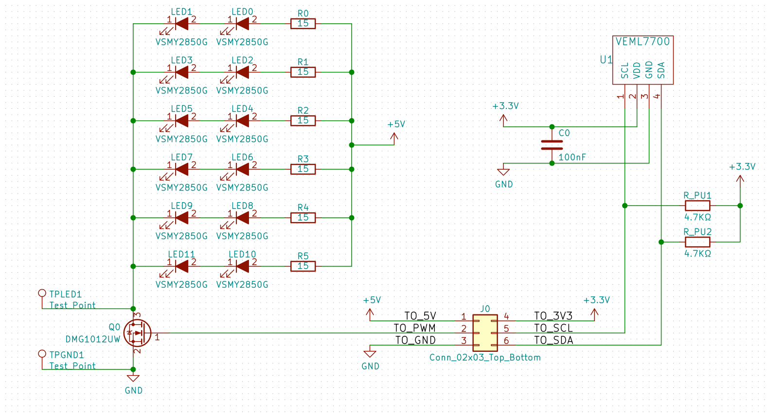 The experience of g5pw, wifasoi and ziongate was essential to develop the PCB with Kicad . The circuit should just power some IR LEDs from the 5V pin of the Raspberry Pi. Moreover, I'd like to control the output from a 3v3 pin; in this way I can tune the emitted light using PWM.
All the project files are on Gitlab.
Choosing the components among those available online was like finding a needle in a haystack; anyway I picked: I componenti che ho trovato nella miriade dei semiconduttori disponibili online sono:
VSMY2850G, 850 nm LED, suitable for PWM, quantity: 10.RK73H-5715, 15 Ohm resistor, quantity: 5.DMG1012UW, n-channel MOSFET, quantity: 1.DS1031-03, 3 pin connector, quantity: 1. too small
Note on component selection
A (tedious) work of datasheet reading on several supplier's websites until I found those that would fit together.
I first picked the IR LEDs, comparing datasheets on how much light they emit with respect to the specs of some IR LEDs I have here. 10 LED looked like the right amount to have (at least) twice as much (emitted) light with respect to version 0. With this information, I computed how many I can put in series (two at most) and power using the 5V pin. I then selected the mosfet basing on the amount of current the LEDs would draw (and the need of using PWM).
In choosing the components I made sure that they would not be too small, since I do not have experience in SMT soldering.
PCB Design
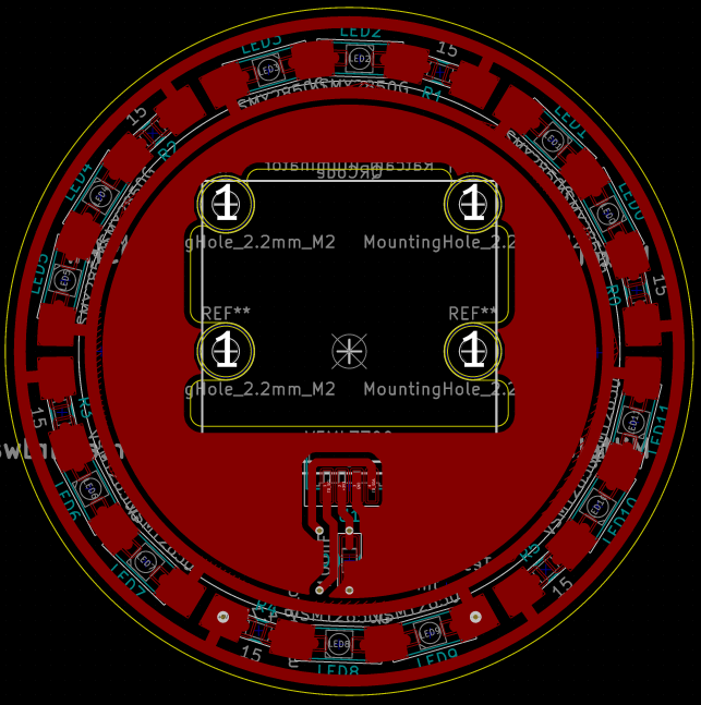 I wanted to arrange the LED in a circular fashion, but Kicad does not provide suitable tools to do so; it is not possible to draw curves with traces or pours. I took inspiration from this project to draw circular elements with Kicad.
At the beginning I had written the bare minimum code that was need to make circular tracks, but afterwards I realized that to align correctly the components and compute the fills I needed a more extensive support for polar coordinates. Hence, I wrote a few classes to manipulate chords and circular sectors, and an extra, more “pythonic” Kicad interface. The set of scripts is on Gitlab. It includes:
cad.pydata model and Kicad object abstraction (limited to what is needed for this project only)pcb.pyconversion from and to Kicadpolar.pygeometric primitivesradial_illuminator.pyconfigurable placer and router for a Ratcam-like illuminator circuit.
Kicad can be controlled in python, but documentation is scarce and often one has to inspect the source code of Kicad to understand what a certain method does. Objects are transported via Swig directly from C++ to python, and therefore they are not exactly trivial to use. Some very useful links for people that want to go down the same road:
- Kicad scripting blog: probably the best place on web to learn how to write Kicad scripts, even better that Kicad's own documentation.
- Studio clock , analogous project
- footprint QR code wizard in Kicad.
- Bug report in Kicad beta, it is not possible to read a fill outline from python
Placement and routing
 The outline of the placement and routing algorithm follows.
Front components: (LEDs and resistors)
- Compute the angle underlying the pad of each of the front components.
- Arrange the frontal components on a circle of fixed radius, in such a way that the barycenter of the pads lies on the circumference, and the angle underlying two adjacent pads of two different components is constant (they're equally distanced in terms of pad-to-pad angle, not distance).
- Route the nets adding tracks along the given circumference.
- Identify the nets that go to the 5V and mosfet drain (called “power” and “ground” in the code, because it would be ground if it weren't for the mosfet) (something something there was no mosfet when I began coding).
- Trace an extra arc starting from each of the pads that connect to one of the two net (power or ground), and trace a ray to connect them to two more concentric circumferences.
- Add copper pour to each of the LED and resistor pads, tracing a fill that coincides with a circular sector of a fixed angle. For interconnected pads, the sector covers the whole track. Pads that go to power or gound nets get a smaller fill which leaves a gap equal to the default track width.
Back components: (connector, mosfet)
- Place mosfet and connector diametrically opposite.
- Re-orient mosfet and connector in a way that the interconnected pads face the same direction (to connect them with just a single arc).
- Compute the optimal position along the diameter to avoid the components to bleed out of the outline of the fron tracks. This is done taking partially in account overlaps and short, and optimizing the amount of horizontal wiring that needs to be added to connect to power and ground net.
- Connect the connector and the mosfet pads with two arcs.
- Connect with a horizontal track and a via the mosfet and the connector to the ground and power nets respectively.
- Add copper pours around the mosfet pads as for the front components.
I later added QR code and text.
Outline and manufacturing
In the Raspberry Pi's camera module documentation I found the measurements of the camera. I drew the same elements in Kicad, to get the camera lens at the very center. I added footprints for the holes and had the PCB manufactured by Elecrow. I add here the settings that wifasoi recommended, since I found different opinions on how to export for Elecrow.
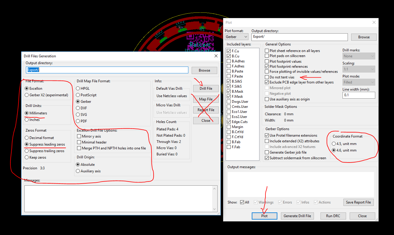
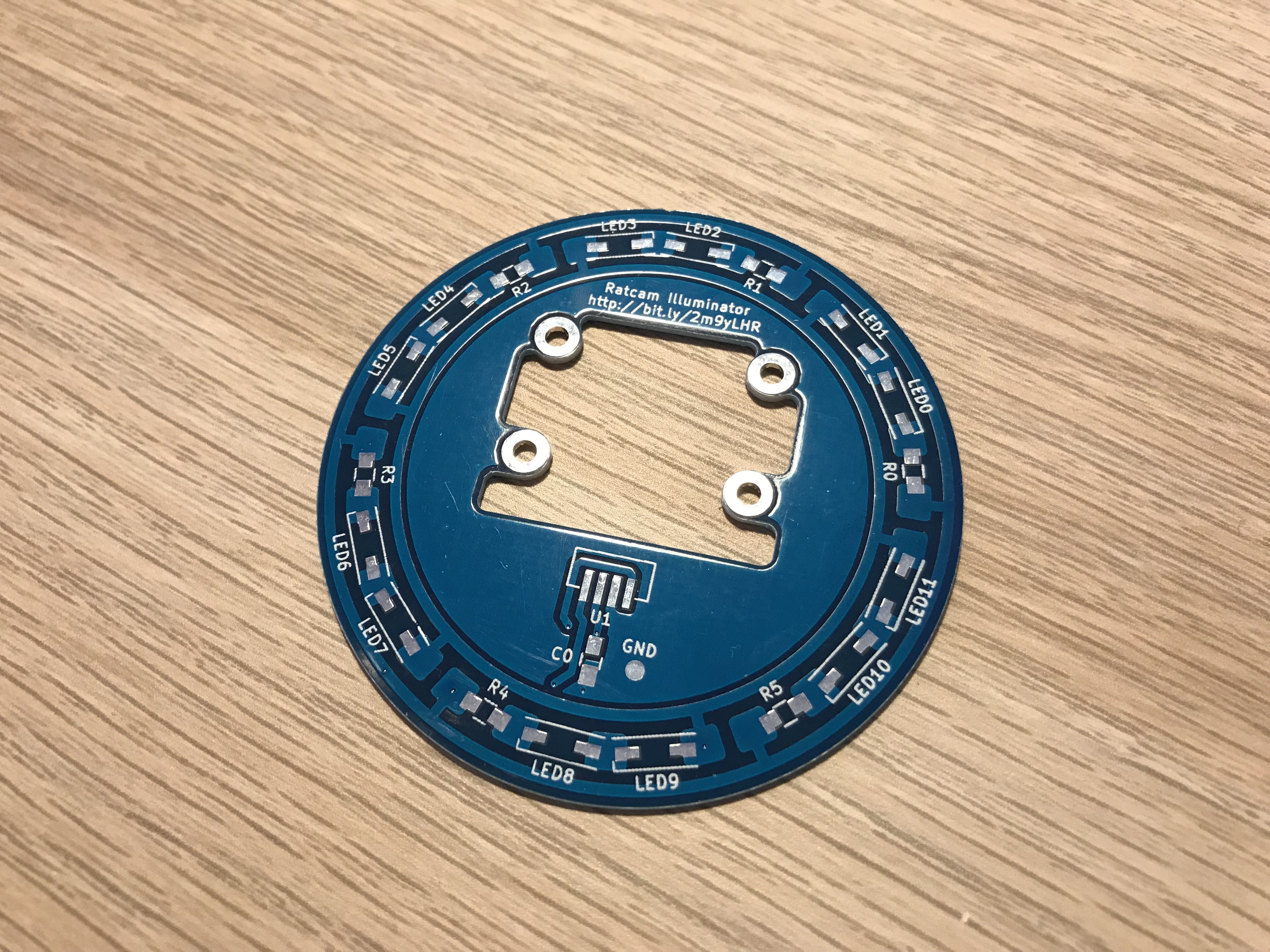
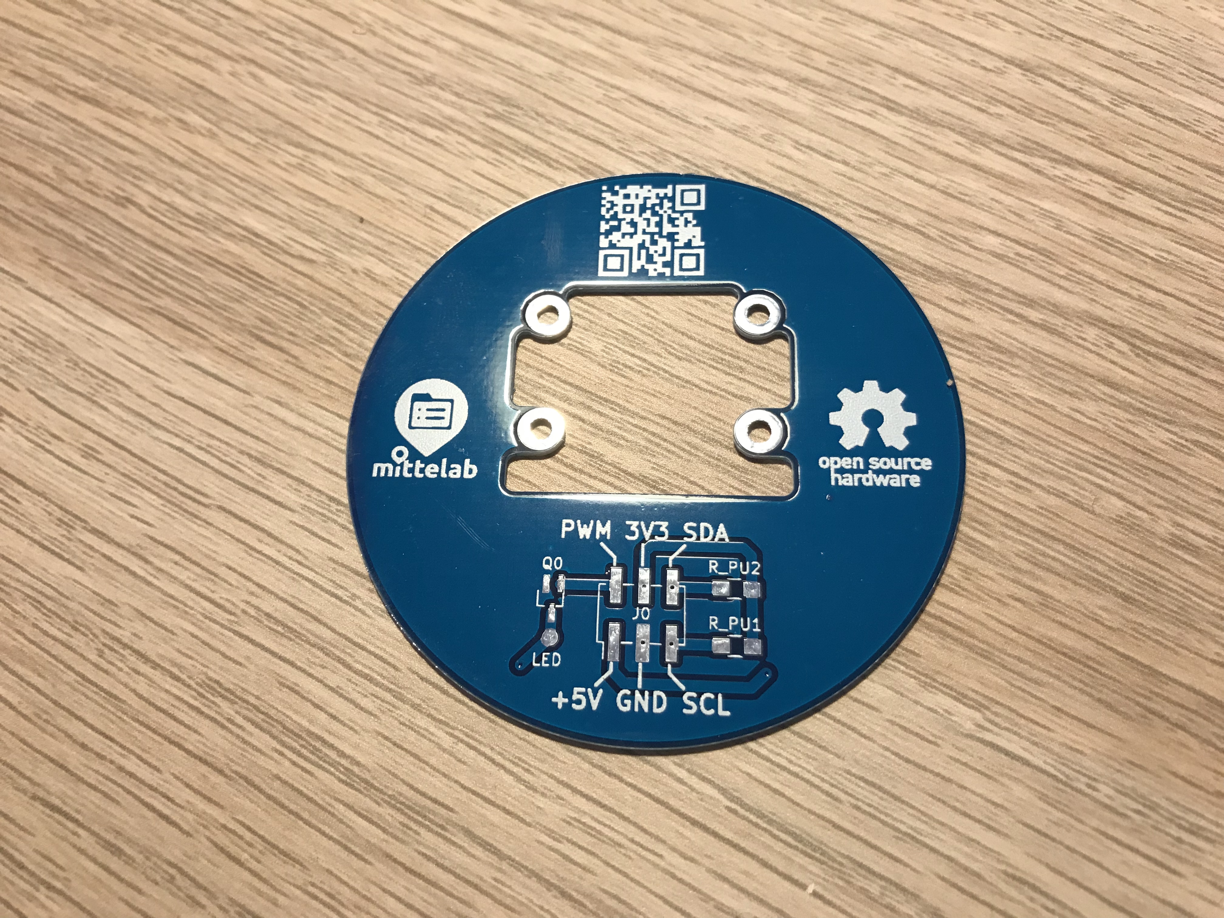
Assembly and limitations
While assembling the illuminator I realized there are several limitations:
- The camera is upside down with respect to the title “Ratcam Illuminator” :D
- The pin header is terribly small (1.27 mm step), and I don't have the female connector for it; I soldered the cables directly to the pads and glued them on for now.
- The pin header is on one side of the camera connector, and not below the flex cable (which makes the whole design a bit more voluminous).
Among the changes to follow, I'll rearrange the components.

PWM LED control
It seems the mosfet I'm using works well in PWM mode. I did some tests with the WiringPi library]]. It seems RPi.GPIO uses software PWM, which consumes a bit extra CPU, but wiringPi and the gpio tool can exploit the hardware PWM on physical pin 12. I wrote a short C++ (C would've been enough) program which oscillates linearly the hardware PWM duty cycle, and recorded the outcome.
PWM wants sudo
Important: setting and writing hardware PWM mode requires superuser privileges. gpio is SUID, so no problem, but my snippet must be run as sudo.
Install the wiringpi library to compile:
- setup.sh
sudo apt-get install wiringpi build-essential
g++ -lwiringPi oscillate.cpp -o oscillate
sudo ./oscillate
- oscillate.cpp
#include <wiringPi.h>
#include <iostream>

int main() {
	wiringPiSetupPhys();
	pinMode(12, PWM_OUTPUT);
	std::div_t div;
	for (int i = 0; ; i = (i + 1) % 2048, div = std::div(i, 1024), delay(1)) {
		const int duty_cycle = div.rem * (1 - 2 * div.quot) + 1024 * div.quot;
		pwmWrite(12, duty_cycle);
		if (i % 64 == 0) {
			std::cout << int(100.f * duty_cycle / 1024.f) << std::endl;
		}
	}
	return 0;
}
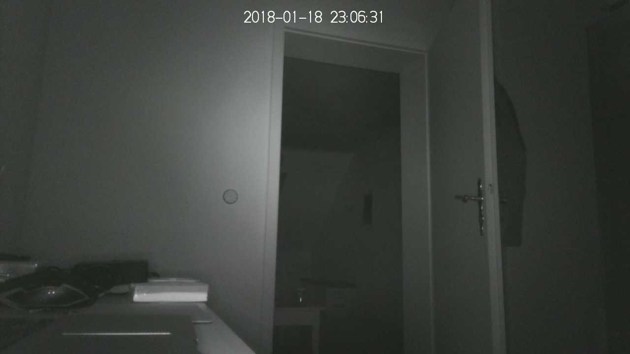
The result follows. Note how the illumination is more than enough to record videos and photos with Ratcam.