Indice
MIDI Accordion (aka. Mi[di]atonerca)
We got the idea to develop an electronic MIDI diatonic accordion (in Slovenian known under the name “frajtonerca”) and planned to turn it into reality at PIFcamp 2017. We knew that building an accordion in one week time would be very ambitious, but why not try it anyway?
Many people asked us about why we decided to build the accordion or what we planned to do with it. Here are some of the main objectives:
- Affordable child toy.
- Having an easier way to learn new songs.
- Affordable and configurable solution for “recording scores” when an expert is playing.
- Ability to practice anywhere.
- Ability to play at any time.
- Learning to play a chromatic accordion just for fun without spending another few thousand EUR for one.
- Get arbitrary sound of it!
Why the MIDI accordion?
Let me elaborate a bit further on the above mentioned objectives.
Existing solutions
There are certain commercial products out there. For example Roland FR18. No clue what the original price was, but it's apparently no longer being sold, it's missing some buttons in the fourth row (like Es on CFB model). For a reasonable price I would probably even buy it.
In Slovenia there are a couple of commercial solutions available for building a MIDI system into an existing accordion. The accordion itself costs anywhere between 2.500 and 5.000+ EUR. The MIDI system alone would be around 1.500 EUR and would not even let us extract the push/pull direction or the exact button being pressed.
The most well-known solution seems to be Totter MIDI. Others include HDS, Blueline MIDI, Apolon, maybe something else I've never heard of. Koren also made some MIDI accordions (as well as really cute free app for iOS and Android which you should try), but apparently stopped producing them due to lack of demand at the price range. According to some testers the sound was much better than from Totter MIDI, but it had unacceptable latency.
But buying an existing product takes all the flexibility and fun away, doesn't it?
About the project
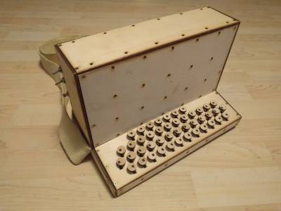
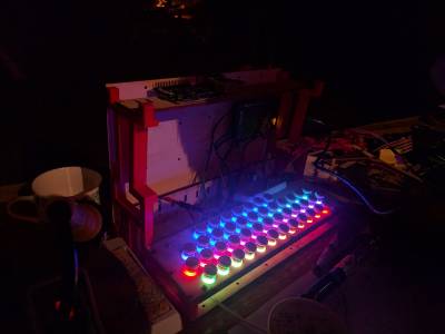
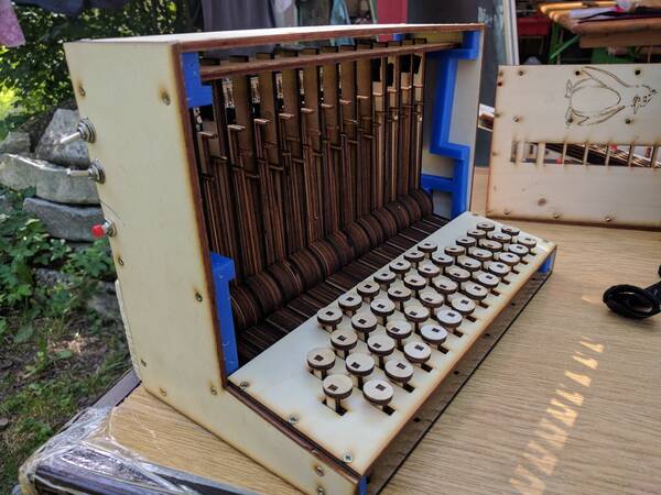
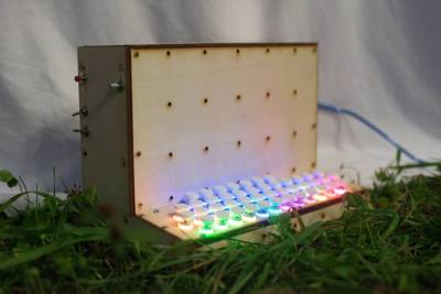
One problem was that we didn't know which button trigger method to use, and brought two options to the camp. Eventually we implemented both, and suddenly turned up with two accordions: one with mechanical levers that trigger photointerrupters, and one with illuminated electric pushbuttons.
Both accordions are mostly laser-cut from 3mm and 4mm plates. The laser cutter is a fantastic device: it cuts highly complex patterns in plates with laser sharp accuracy at such fabulous speeds, that 99.9999% of your time is spent in pre-processing drawings until it gets finally accepted by the cutter.
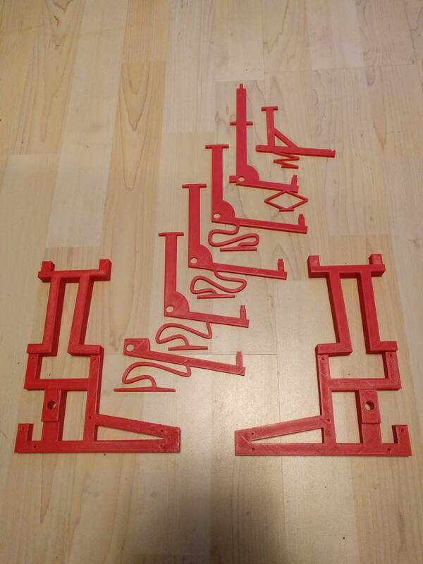
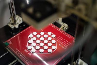
The plates have to be attached to something, and that “something” are two big 3D printed structures with numerous carefully spaced holes.
The keyboard houses four rows of buttons. Why four? Accordions come in various sizes, with five rows for chromatic ones, and anything from one to four for diatonic accordions. We designed a system that could potentially accomodate up to five rows, and in constructing the four-row diatonic accordion, the spaces for the fifth row were used as reinforcements and lever aligners instead.
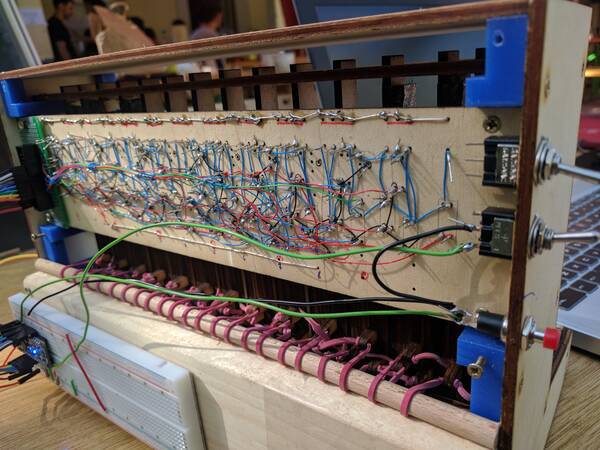
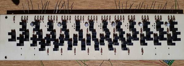
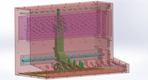
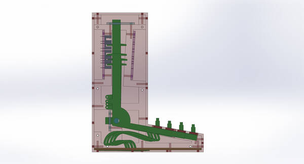
Each button is mounted on a L-shaped lever with pins on either end of the top. The pins open or close a photointerrupter, to trigger notes. The design allows to place photointerrupters on both sides of the levers, with the idea of registering velocity by measuring the button travel time from one end to another. In the current implementation, only the rear side is filled with photointerrupters.
After pressing a lever, it has to bounce back to its original position by some force. The idea was to incorporate a blade spring in the lever design itself, which can be easily laser-cut or 3D printed in one piece. Several designs have been studied; eventually, one of the blade spring designs was chosen in conjunction with small rubber springs at the back to obtain a good mechanical response.
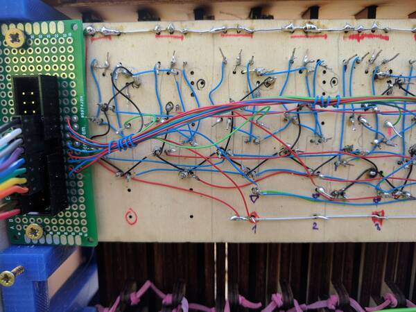
The photointerrupters are mounted on a laser-cut wooden plate that serves as a PCB. Actually, without the printed circuits which leaves just the B (for board). We thought it would be more effective to do wire-wrapping and soldering pins ourselves. Oh man, that took forever! But the final result is so rewarding :)
The photointerrupters are grouped in six sets of eight interrupters each. Each set is activated by a transistor driven by a digital output, and an interrupter of each set is read out by a digital input. This way, 6+8=14 pins suffice to read out all 44 buttons of the accordion. An Arduino Nano already has enough pins to perform this task.
The design was drawn in Solidworks. Some CAD renderings are shown here, in an attempt to visualize the lever function.
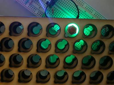
The illuminated accordion uses pushbuttons with RGB LEDs mounted next to it under a semi-transparent ring, in order to evenly distribute the light from the LED. The top of the pushbutton is 3D printed, in order to mimick the diameter and shape of that of a real accordion.
Further plans
- Measurements:
- delay/latency between button press and MIDI message
- delay/latency between the MIDI message and generation of the sound on RPi / Windows / Mac
- force and travel distance measurement of key presses on a real diatonic accordion
- Electronic design
- Make real PCBs
- Polish design of the LEDs
- Full PCB, including charger, audio amplifier, MIDI-out, …
- Mechanical design:
- Improve lever design
- Add finger joints to the box and cut holes for connectors
- Software:
- Ability to easily upload new songs
- Ability to easily extract exact key presses + scores
- Best way to configure stuff: change key layout, tuning, instrument, …
- Implement speed and vibrato, both mechanically and in software
- Some examples:
Credits
Authors of the project:
- Mojca Miklavec, Slovenia
- Vincent Groenhuis, The Netherlands
Thanks to various individual and organisations who helped us make our project a reality:
- Mittelab, a very friendly hackerspace in Trieste where most the parts were 3D printed and laser-cut with extensive help of other members; with a special thank-you going to:
- Aljaž Srebrnič for help with KiCad, 3D printing, laser-cutting, and establishing the hackerspace in the first place
- Luca Cristaldi, the owner of the laser cutter who also devoted a lot of his time helping with 2D design and laser cutting procedures and preparation
- Ljudmila with its gorgeous PIF Camp where we were provided with all the required tools and personal support, located next to refreshing Soča river and away from our daily jobs, which made it possible for us to concentrate on the project for nearly the whole week
- Staš Vrenko and Clemens helped us fight with KiCad, etching and drilling our PCB
- Faculty of Computer and Information Science at University of Ljubljana
- Gašper Fele-Žorž for help with electronics, for letting us use their workshop and the very special wire-wrapping tool (reducing the need for a proper PCB which could otherwise not be finished in time)
- Matjaž Vencelj (also Mojca's thesis supervisor) for help with Arduino, electronics, design, a lot of moral support …
Open-source projects:
- MIDI Accordion project by Brendan Vavra with lots of inspiration and very useful instructions
- SamplerBox for an out-of-the-box solution for audio synthesis from MIDI
- Arduino, Raspberry PI, KiCad, ConTeXt + MetaPost, …
Material
- Photoelectric Switch ITR-9608
- LEDs
- round LEDs
- https://www.sparkfun.com/products/12986 (3 USD / 5 pcs)
- https://www.pololu.com/product/2535 (5 USD / 10 pcs)
- https://www.aliexpress.com/store/product/Flat-hat-WS2812D-5mm-RGB-WS2811-LEDs-RGB-full-color-with-WS2811-IC-built-in/701799_32696884482.html (12 USD / 100 pcs + 17 USD shipping; funny shape), https://www.aliexpress.com/item/Flat-hat-WS2812D-5mm-RGB-WS2811-LEDs-RGB-full-color-with-WS2811-IC-built-in/32720348682.html (7 USD shipping)
- SMD only
- with heatsink
